Light Notes 9th Science Lesson 4 Notes in English
Light Notes 9th Science Lesson 4 Notes in English
Introduction
- Light is a form of energy which travels as electromagnetic waves.
- The branch of physics that deals with the properties and applications of light is called optics.
- In our day to day life we use number of optical instruments.
- Microscopes are inevitable in science laboratories.
- Telescopes, binoculars, cameras and projectors are used in educational, scientific and entertainment fields.
- In this lesson, you will learn about spherical mirrors (concave and convex).
- Also, you will learn about the properties of light, namely reflection and refraction and their applications.
Reflection of Light
- Light falling on any polished surface such as a mirror, is reflected.
- This reflection of light on polished surfaces follows certain laws and you have studied about them in your lower classes.
- Let us study about them little elaborately here.
Laws of reflection
- Consider a plane mirror MM’ as shown in Figure 6.1.
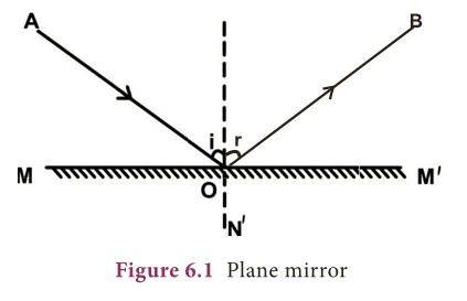
- Let AO be the light ray incident on the plane mirror at O. The ray AO is called incident ray.
- The plane mirror reflects the incident ray along OB. The ray OB is called reflected ray.
- Draw a line ON at O perpendicular to MM’. This line ON is called normal.
- The angle made by the incident ray with the normal (i = angle AON) is called angle of incidence.
- The reflected ray OB makes an angle (r = angle NOB) with the normal and this is called angle of reflection.
- From the figure you can observe that the angle of incidence is equal to the angle of reflection.
![]()
- Also, the incident ray, the reflected ray and the normal at the point of incidence all lie in the same plane.
- These are called the laws of reflection.
- Laws of reflection are given as: The incident ray, the reflected ray and the normal at the point of incidence, all lie in the same plane.
- The angle of incidence is equal to angle of reflection.
Lateral inversion
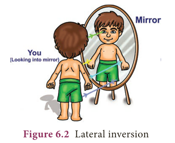
- You might have heard about inversion.
- But what is lateral inversion? The word lateral comes from the Latin word latus which means side.
- Lateral inversion means sidewise inversion.
- It is the apparent inversion of left and right that occurs in a plane mirror.
- Why do plane mirrors reverse left and right, but they do not reverse up and down? Well, the answer is surprising.
- Mirrors do not actually reverse left and right and they do not reverse up and down also.
- What actually mirrors do is reverse inside out.
- Look at the image below (Figure 6.2) and observe the arrows, which indicate the light ray from the object falling on the mirror.
- The arrow from the object’s head is directed towards the top of the mirror and the arrow from the feet is directed towards the bottom.
- The arrow from left hand goes to the left side of the mirror and the arrow from the right hand goes to the right side of the mirror.
- Here, you can see that there is no switching. It is an optical illusion.
- Thus, the apparent lateral inversion we observe is not caused by the mirror but the result of our perception.
Real and Virtual Image

- If the light rays coming from an object actually meet, after reflection, the image formed will be a real image and it is always inverted.
- A real image can be produced on a screen.
- When the light rays coming from an object do not actually meet, but appear to meet when produced backwards, that image will be virtual image.
- The virtual image is always erect and cannot be caught on a screen (Figure 6.3).
Activity 1
- Stand before the mirror in your dressing table or the mirror fixed in a steel almirah. Do you see your whole body?
- To see your entire body in a mirror, the mirror should be atleast half of your height.
- Height of the mirror= Your height/2.
Curved Mirrors
- We studied about laws of reflection. These laws are applicable to all types of reflecting surfaces including curved surfaces.
- In your earlier classes, you have studied that there are many types of curved mirrors, such as spherical and parabolic mirrors.
- The most commonly used type of curved mirror is spherical mirror.
Spherical mirrors
- In curved mirrors, the reflecting surface can be considered to form a part of the surface of a sphere.
- Such mirrors whose reflecting surfaces are spherical are called spherical mirrors.
- In some spherical mirrors the reflecting surface is curved inwards, that is, it faces towards the centre of the sphere.
- They are called concave mirrors.
- In some other mirrors, the reflecting surface is curved outward. They are called convex mirror.
Image formed by spherical mirrors
Activity 2
- Hold a concave mirror in your hand (or place it in a stand).
- Direct its reflecting surface towards the sun. Direct the light reflected by the mirror onto a sheet of paper held not very far from the mirror.
- Move the sheet of paper back and forth gradually until you find a bright, sharp spot of light on the paper.
- Position the mirror and the paper at the same location for few moments. What do you observe?
- Why does the paper catches fire?
- We saw that the parallel rays of sun light could be focused at a point using a concave mirror.
- Now let us place a lighted candle and a white screen in front of the concave mirror. Adjust the position of the screen.
- Move the screen front and back. Note the size of the image and its shape. You can see a small and inverted image.
- Slowly bring the candle closer to the mirror. What do you observe? As you bring the object closer to the mirror the image becomes bigger.
- Try to locate the image when you bring the candle very close to the mirror.
- Are you able to see an image on the screen? Now look inside the mirror.
- What do you see? An erect magnified image of the candle is seen.
- In some positions of the object an image is obtained on the screen. However, at some positions of the object no image is obtained.
- It is clear that the behaviour of the concave mirror is much more complicated than the plane mirror.
- However, with the use of geometrical technique we can simplify and understand the behaviour of the image formed by a concave mirror.
- In the case of plane mirror, we used only two rays to understand how to get full image of a person.
- But, for understanding the nature of image formed by a spherical mirrors we need to look at four specific rules.
Rules for the construction of image
- To find the position and nature of the image formed by a spherical mirror, we need to know the following rules.
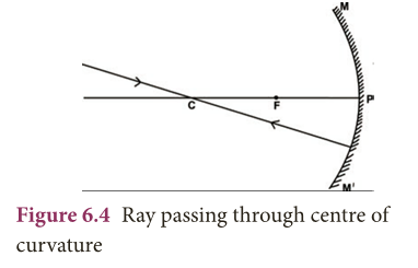
- Rule 1: A ray passing through the centre of curvature is reflected back along its own path (Figure 6.4).
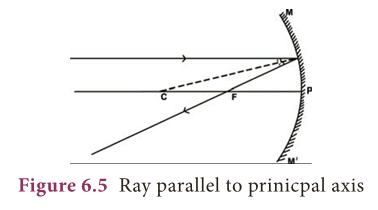
- Rule 2: A ray parallel to the principal axis passes through or appears to be coming from the principal focus (in case of convex mirror) after reflection (Figure 6.5).
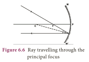
- Rule 3: A ray passing through the focus gets reflected and travels parallel to the principal axis (Figure 6.6).
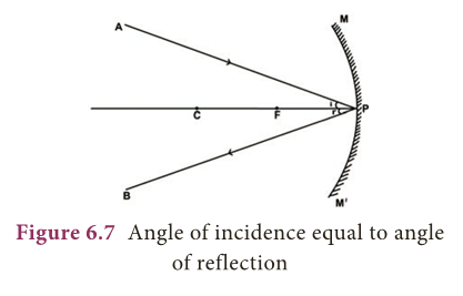
- Rule 4: A ray incident at the pole of the mirror gets reflected along a path such that the angle of incidence (APC) is equal to the angle of reflection (BPC) (Figure 6.7).
Concave Mirror
Image Formation
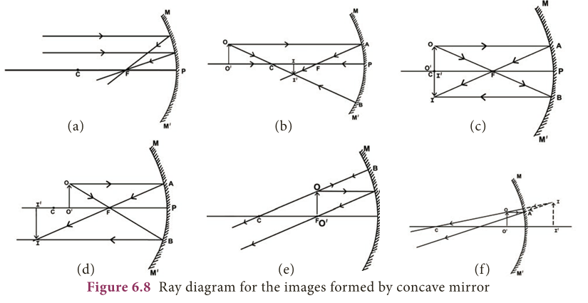
- We shall now find the position, size and nature of image by drawing the ray diagram for a small linear object placed on the principal axis of a concave mirror at different positions.
- Case–I: When the object is far away (at infinity), the rays of light reaching the concave mirrors are parallel to each other (Figure 6.8a).
- Position of the Image: The image is formed at the principal focus F.
- Nature of the Image: It is real, inverted and highly diminished in size.
- Case–II: When the object is beyond the centre of curvature (Figure 6.8b).
- Position of the image: Between the principal focus F and centre of curvature C.
- Nature of the image: Real, inverted and smaller than object.
- Case – III: When the object is at the centre of curvature (Figure 6.8c).
- Position of the image: The image is at the centre of curvature itself.
- Nature of the image: It is real, inverted and same size as the object.
- Case – IV: When the object is in between the centre of curvature C and principal focus F (Figure 6.8d).
- Position of the image: The image is beyond C
- Nature of the image: It is real inverted and magnified.
- Case – V: When the object is at the principal focus F (Figure 6.8e).
- Nature of the image: No image can be captured on the screen nor any virtual image can be seen.
- Case – VI: When the object is in between the focus F and the pole P (Figure 6.8f).
- Position of the image: The image is behind the mirror.
- Nature of the image: It is virtual, erect and magnified.
Sign convention for measurement of distances
- We follow a set of sign conventions called the cartesian sign convention to measure distances in ray diagram.
- In this convention, the pole(P) of the mirror is taken as the origin.
- The principal axis is taken as the X-axis of the coordinate system (Figure 6.9).
- The object is always placed on the left side of the mirror.
- All distances are measured from the pole of the mirror.
- Distances measured in the direction of incident light are taken as positive and those measured in the opposite direction are taken as negative.
- All distances measured perpendicular to and above the principal axis are considered to be positive.
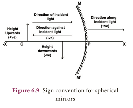
- All distances measured perpendicular to and below the principal axis are considered to be negative.

Mirror equation
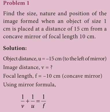
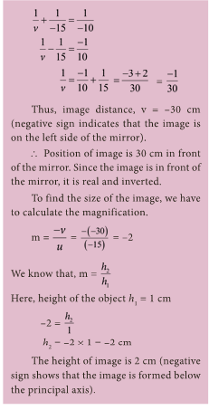
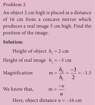
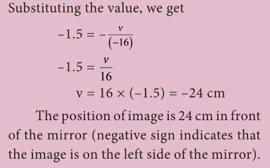
- The expression relating the distance of the object (u), distance of the image (v) and the focal length (f) of a spherical mirror is called the mirror equation. It is given as:

Linear magnification (m)
- Magnification produced by a spherical mirror gives how many times the image of an object is magnified with respect to the object size.
- It can be defined as the ratio of the height of the image (hi) to the height of the object (ho).

- The magnification can be related to object distance (u) and the image distance (v).

- Note: A negative sign in the value of magnification indicates that the image is real.
- A positive sign in the value of magnification indicates that the image is virtual.
Uses of concave mirror
- Dentist’s head mirror: In dentist’s head mirror, a parallel beam of light is made to fall on the concave mirror.
- This mirror focuses the light beam on a small area of the body (such as teeth, throat etc.).
- Make-up mirror: When a concave mirror is held near the face, an upright and magnified image is seen. Here, our face will be seen magnified.
- Other applications: Concave mirrors are also used as reflectors in torches, head lights in vehicles and search lights to get powerful beams of light.
- Large concave mirrors are used in solar heaters.
Convex Mirror
Image Formation
- Any two rays can be chosen to draw the position of the image in a convex mirror (Figure 6.10): a ray that is parallel to the principal axis (rule 1) and a ray that appears to pass through the centre of curvature (rule 2).
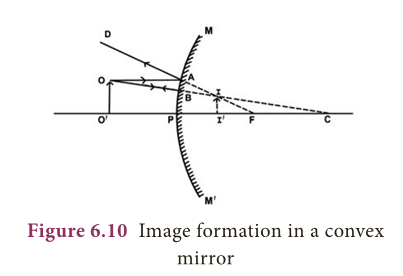
- Note: All rays behind the convex mirror shall be shown with dotted lines.
- The ray OA parallel to the principal axis is reflected along AD. The ray OB retraces its path.
- The two reflected rays diverge but they appear to intersect at I when produced backwards.
- Thus II’ is the image of the object OO’. It is virtual, erect and smaller than the object.
Activity 3
- Take a convex mirror. Hold it in one hand.
- Hold a pencil close to the mirror in the upright position in the other hand.
- Observe the image of the pencil in the mirror. Is the image erect or inverted?
- Is it diminished or enlarged?
- Move the pencil slowly away from the mirror.
- Does the image become smaller or larger? What do you observe?
Uses of convex mirrors
- Convex mirrors are used as rear-view mirrors in vehicles. It always forms a virtual, erect, small-sized image of the object.
- As the vehicles approach the driver from behind, the size of the image increases.
- When the vehicles are moving away from the driver, then image size decreases.
- A convex mirror provides a much wider field of view (it is the observable area as seen through eye / any optical device such as mirror) compared to plane mirror.
- Convex mirrors are installed on public roads as traffic safety device.
- They are used in acute bends of narrow roads such as hairpin bends in mountain passes where direct view of oncoming vehicles is restricted.
- It is also used in blind spots in shops.
Problem 3
- A car is fitted with a convex mirror of focal length 20 cm. Another car is 6 m away from the first car.
- Find the position of the second car as seen in the mirror of the first. What is the size of the image if the second car is 2 m broad and 1.6 m high?


Speed of light
- In early seventeenth century, the Italian scientist Galileo Galilee (1564-1642) tried to measure the speed of light.
- In 1665, the Danish astronomer Ole Roemer first estimated the speed of light by observing one of the twelve moons of the planet Jupiter.
- He estimated the speed of light to be about 220,000 km per second.
- In 1849, the first land based estimate was made by Armand Fizeau.
- Today the speed of light in vacuum is known to be almost exactly 300,000 km per second.
Refraction of light
Activity 4
- Refraction of light at air – water interface
- Put a straight pencil into a tank of water or beaker of water at an angle of 45° and look at it from one side and above. How does the pencil look now?
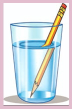
- The pencil appears to be bent at the surface of water.
- This activity explains the refraction of light.
- The bending of light rays when they pass obliquely from one medium to another medium is called refraction of light.
- Light rays get deviated from their original path while entering from one transparent medium to another medium of different optical density.
- This deviation (change in direction) in the path of light is due to the change in velocity of light in the different medium.
- The velocity of light depends on the nature of the medium in which it travels.
- Velocity of light is more in a rarer medium (low optical density) than in a denser medium (high optical density).
Refraction of light from a plane transparent surface
- When a ray of light travels from optically rarer medium to optically denser medium, it bends towards the normal. (Figure 6.11a).
- When a ray of light travels from an optically denser medium to an optically rarer medium it bends away from the normal. (Figure 6.11b).
- A ray of light incident normally on a denser medium, goes without any deviation. (Figure 6.11c).
The laws of refraction of light
- Laws of refraction, also known as Snell’s law of refraction are given below as:
- The incident ray, the refracted ray and the normal to the interface of two transparent media at the point of incidence, all lie in the same plane.
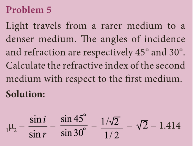
- The ratio of the sine of the angle of incidence to the sine of the angle of refraction is a constant for a light of given colour and for the given pair of media.
- If i is the angle of incidence and r is the angle of refraction, then this constant is called the refractive index of the second medium with respect to the first medium.
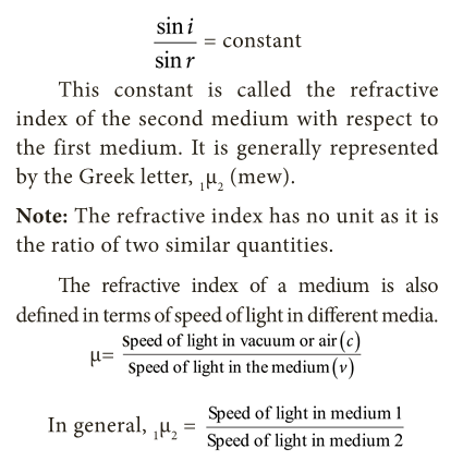
- It is generally represented by the Greek letter, 1µ2 (mew).
- Note: The refractive index has no unit as it is the ratio of two similar quantities.
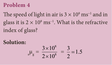
- The refractive index of a medium is also defined in terms of speed of light in different media.

Total Internal Reflection
- When light travels from denser medium into a rarer medium, it gets refracted away from the normal.
- While the angle of incidence in the denser medium increases the angle of refraction also increases and it reaches a maximum value of r = 90º for a particular value.
- This angle of incidence is called critical angle (Figure 6.12).

- The angle of incidence at which the angle of refraction is 90º is called the critical angle.
- At this angle, the refracted ray grazes the surface of separation between the two media.
- When the angle of incidence exceeds the value of critical angle, the refracted ray is not possible.
- Since r > 90º the ray is totally reflected back to the same medium. This is called as total internal reflection.
Conditions to achieve total internal reflection
- In order to achieve total internal refelection the following conditions must be met.
- Light must travel from denser medium to rarer medium. (Example: From water to air).
- The angle of incidence inside the denser medium must be greater than that of the critical angle.
Total internal reflection in nature
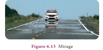
- Mirage: On hot summer days, patch of water may be on the road. This is an illusion.
- In summer, the air near the ground becomes hotter than the air at higher levels.
- Hotter air is less dense, and has smaller refractive index than the cooler air.
- Thus, a ray of light bends away from the normal and undergoes total internal reflection.
- Total internal reflection is the main cause for the spectacular brilliance of diamonds and twinkling of stars.
Optical fibres:
- Optical fibres are bundles of high-quality composite glass/quartz fibres. Each fibre consists of a core and cladding.
- The refractive index of the material of the core is higher than that of the cladding.
- Optical fibres work on the phenomenon of total internal reflection.

- When a signal in the form of light is directed at one end of the fibre at a suitable angle, it undergoes repeated total internal reflection along the length of the fibre and finally comes out at the other end.
- Optical fibres are extensively used for transmitting audio and video signals through long distances.
- Moreover, due to their flexible nature, optical fibers enable physicians to look and work inside the body through tiny incisions without having to perform surgery.
MORE TO KNOW:
AMBULANCE
- The most common usage of mirror writing can be found on the front of ambulances, where the word “AMBULANCE” is often written in very large mirrored text.
Stellar objects
- Stellar objects are at an infinite distance.
- Therefore, the image formed by a concave mirror would be diminished, and inverted.
- Yet, astronomical telescopes use concave mirrors.
Rear view mirror
- In the rear view mirror, the following sentence is written. “Objects in the mirror are closer than they appear”. Why?
Bioluminescence
- Some organisms can make their own light too?
- This ability is called bioluminescence.
- Worms, fish, squid, starfish and some other organisms that live in the dark sea habitat glow or flash light to scare off predators.
The Father of Fibre Optics
- An Indian-born physicist Narinder Kapany is regarded as the Father of Fibre Optics.
EXTRA POINTS:
- Spherical Mirror: A reflecting surface which is a part of a sphere whose inner or outer surface is reflecting.
- Concave Mirror: Part of a hollow sphere whose outer part is silvered and/or inner part is the reflecting surface.
- Convex Mirror: Part of a hollow sphere whose inner part is silvered and/or outer part is the reflecting surface.
- Centre of curvature: The centre of the hollow sphere of which the spherical mirror forms a part.
- Radius of curvature: The radius of the hollow sphere of which the spherical mirror forms a part.
- Pole: The midpoint of the spherical mirror.
- Aperture: The diameter of the circular rim of the mirror.
- Principal axis: The normal to the centre of the mirror is called the principal axis.
- Principal focus: The point on the principal axis of the spherical mirror where the rays of light parallel to the principal axis meet or appear to meet after reflection from the spherical mirror.