ELECTRIC CHARGE AND ELECTRIC CURRENT Notes 9th Science Lesson 13 Notes in English
ELECTRIC CHARGE AND ELECTRIC CURRENT
Introduction
- Like mass and length, electric charge also is a fundamental property of all matter.
- We know that matter is made up of atoms and molecules.
- Atoms have particles like electrons, protons and neutrons.
- By nature, electrons and protons have negative and positive charge respectively and neutrons do not have charge.
- An electric current consists of moving electric charges.
- Electricity is an important source of energy in the modern times.
- In this lesson, we will study about electric charges, electric current, electric circuit diagram and the effects of electric current.
Electric charges
- Inside each atom there is a nucleus with positively charged protons and charge less neutrons and negatively charged electrons orbiting the nucleus.
- Usually there are as many electrons as there are protons and the atoms themselves are neutral.
- If an electron is removed from the atom, the atom becomes positively charged. Then it is called a positive ion.
- If an electron is added in excess to an atom then the atom is negatively charged and it is called negative ion.
- When you rub a plastic comb on your dry hair, the comb obtains power to attract small pieces of paper, is it not?
- When you rub the comb vigorously, electrons from your hair leave and accumulate on the edge of the comb.
- Your hair is now positively charged as it has lost electrons and the comb is negatively charged as it has gained electrons.
Measuring electric charge
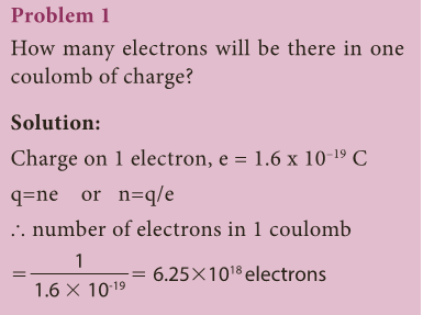
- Electric charge is measured in coulomb and the symbol for the same is C.
- The charge of an electron is numerically a very tiny value.
- The charge of an electron (represented as e) is the fundamental unit with a charge equal to 1.6 × 10⁻¹⁹ C.
- This indicates that any charge (q) has to be an integral multiple (n) of this fundamental unit of electron charge (e). q = ne.
- Here, n is a whole number.
- Practically, we have µC (micro coulomb), nC (nano coulomb)and pC (pico coulomb) as units of electric charge.
- 1 µC = 10-6 C, 1nC=10-9 and 1pC = 10-12C
- Electric charge is additive in nature. The total electric charge of a system is the algebraic sum of all the charges located in the system.
- For example, let us say that a system has two charges +5C and –2C. Then the total or net charge on the system is, (+5C) + (–2C) = +3C.
Electric force
- Among electric charges, there are two types of electric force (F): one is attractive and the other is repulsive.
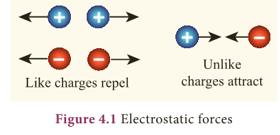
- The like charges repel and unlike charges attract. The force existing between the charges is called as ‘electric force’.
- These forces can be experienced even when the charges are not in contact.
Electric field
- The region in which a charge experiences electric force forms the ‘electric field’ around the charge.
- Often electric field (E) is represented by lines and arrowheads indicating the direction of the electric filed (Fig. 4.2).
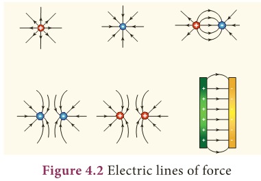
- The direction of the electric field is the direction of the force that would act on a small positive charge.
- Therefore the lines representing the electric field are called ‘electric lines of force’.
- The electric lines of force are straight or curved paths along which a unit positive charge tends to move in the electric field.
- Electric lines of force are imaginary lines. The strength of an electric field is represented by how close the field lines are to one another.
- For an isolated positive charge the electric lines of force are radially outwards and for an isolated negative charge they are radially inwards.
- Electric field at a point is a measure of force acting on a unit positive charge placed at that point.
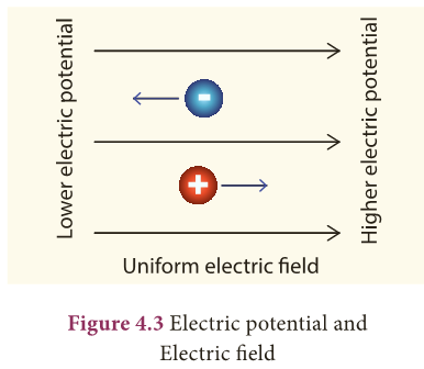
- A positive charge will experience force in the direction of electric field and a negative charge will experience in the opposite direction of electric field.
Electric potential
- Though there is an electric force (either attractive or repulsive) existing among the charges, they are still kept together, is it not?
- We now know that in the region of electric charge there is an electric field.
- Other charges experience force in this field and vice versa.
- There is a work done on the charges to keep them together.
- This results in a quantity called ‘electric potential’.
- Electric potential is a measure of the work done on unit positive charge to bring it to that point against all electrical forces.
Electric current
- When the charged object is provided with a conducting path, electrons start to flow through the path from higher potential to lower potential region.
- Normally, the potential difference is produced by a cell or battery.
- When the electrons move, we say that an electric current is produced.
- That is, an electric current is formed by moving electrons.
Direction of current
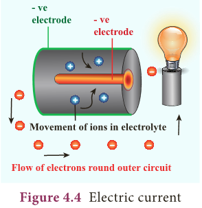
- Before the discovery of the electrons, scientists believed that an electric current consisted of moving positive charges.
- Although we know this is wrong, the idea is still widely held, as the discovery of the flow of electrons did not affect the basic understanding of the electric current.
- The movement of the positive charge is called as ‘conventional current’.
- The flow of electrons is termed as ‘electron current’.
- This is depicted in Figure 4.4.
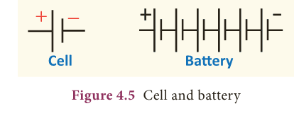
- In electrical circuits the positive terminal is represented by a long line and negative terminal as a short line.
- Battery is the combination of more than one cell (Fig. 4.5).
Measurement of electric current
- We can measure the value of current and express it numerically.
- Current is the rate at which charges flow past a point on a circuit.
- That is, if q is the quantity of charge passing through a cross section of a wire in time t, quantity of current (I) is represented as, I = q/t
- The standard SI unit for current is ampere with the symbol A.
- Current of 1 ampere means that there is one coulomb (1C) of charge passing through a cross section of a wire every one second (1 s).

- 1 ampere = 1 coulomb / 1 second (or) 1 A = 1 C / 1 s = 1Cs-1
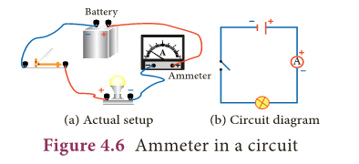
- Ammeter is an instrument used to measure the strength of the electric current in an electric circuit.
- The ammeter is connected in series in a circuit where the current is to be found. .
- The current flows through the positive (+) red terminal of ammeter and leaves from the negative (–) black terminal.
Problem 2
- If, 25 C of charge is determined to pass through a wire of any cross section in 50 s, what is the measure of current?
- Solution: I = q / t = (25 C) / (50 s) = 0.5 C/s = 0.5 A
Problem 3
- The current flowing through a lamp is 0.2A.
- If the lamp is switched on for one hour, what is the total electric charge that passes through the lamp?
Solution:
- I = q / t; q = I x t
- 1hr = 1 x 60 x 60 s = 3600 s
- q = I x t = 0.2 A x 3600 s =720 C
Electromotive force (e.m.f)
- Imagine that two ends of a water pipe filled with water are connected.
- Although filled with water, the water will not move or circle around the tube on its own.
- Suppose, you insert a pump in between and the pump pushes the water, then the water will start moving in the tube.
- Now the moving water can be used to produce some work.
- We can insert a water wheel in between the flow and make it to rotate and further use that rotation to operate machinery.
- Likewise if you take a circular copper wire, it is full of free electrons. However, they are not moving in a particular direction.
- You need some force to push the electrons to move in a direction. The water pump and a battery are compared in Figure 4.7.
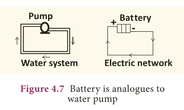
- Devices like electric cells and other electrical energy sources act like pump, ‘pushing’ the charges to flow through a wire or conductor.
- The ‘pumping’ action of the electrical energy source is made possible by the ‘electromotive force, (e.m.f).
- The electromotive force is represented as (ε).
- The e.m.f of an electrical energy source is the work done (W) by the source in driving a unit charge (q) around the complete circuit.
- ε = W/q
- where, W is the work done. The SI unit of e.m.f is joules per coulomb (JC-1) or volt (V).
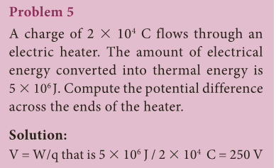
- In other words the e.m.f of an electrical energy source is one volt if one joule of work is done by the source to drive one coulomb of charge completely around the circuit.
Problem 4
- The e.m.f of a cell is 1.5 V. What is the energy provided by the cell to drive 0.5 C of charge around the circuit?
Solution:
- ε = 1.5 V and q 5 0.5 C
- ε = W/q; W 5 ε 3 q;
- Therefore W = 1.5 3 0.5 = 0.75 J
Potential difference (pd)
- One does not just let the circuit connect one terminal of a cell to another.
- Often we connect, say a bulb or a small fan or any other electrical device in an electric circuit and use the electric current to drive them.
- This is how a certain amount of electrical energy provided by the cell or any other source of electrical energy is converted into other form of energy like light, heat, mechanical and so on.
- For each coulomb of charge passing through the light bulb (or any appliances) the amount of electrical energy converted to other forms of energy depends on the potential difference across the electrical device or any electrical component in the circuit.
- The potential difference is represented by the symbol V.
- V = W/q where, W is the work done, i.e., the amount of electrical energy converted into other forms of energy measured in joule and q is amount of charge measured in coulomb.
- The SI unit for both e.m.f and potential difference is the same i.e., volt (V).
- Voltmeter is an instrument used to measure the potential difference.
- To measure the potential difference across a component in a circuit, the voltmeter must be connected in parallel to it.
- Say, you want to measure the potential difference across a light bulb, you need to connect the voltmeter as given in Figure 4.8.
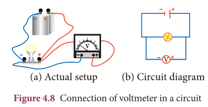
- Note the positive (+) red terminal of the voltmeter is connected to the positive side of circuit and the negative (–) black terminal is connected to the negative side of the circuit across a component (light bulb in the above illustration).
Resistance
- The Resistance (R) is the measure of opposition offered by the component to the flow of electric current through it.
- Different electrical components offer different electrical resistance.
- Metals like copper, aluminium etc., have very much negligible resistance.
- That is why they are called good conductors.
- On the other hand, materials like nicrome, tin oxide etc., offer high resistance to the electric current.
- We also have a category of materials called insulators; they do not conduct electric current at all (glass, polymer, rubber and paper).
- All these materials are needed in electrical circuits to have usefulness and safety in electrical circuits.
- The SI unit of resistance is ohm with the symbol (Ω).
- One ohm is the resistance of a component when the potential difference of one volt applied across the component drives a current of one ampere through it.
- We can also control the amount of flow of current in a circuit with the help of resistance.
- Such components used for providing resistance are called as ‘resistors’. The resistors can be fixed or variable.
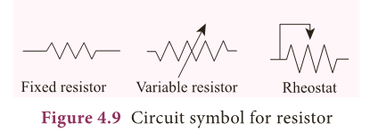
- Fixed resistors have fixed value of resistance, while the variable resistors like rheostats can be used to obtain desired value of resistance (Fig. 4.9).
Electric circuit diagram
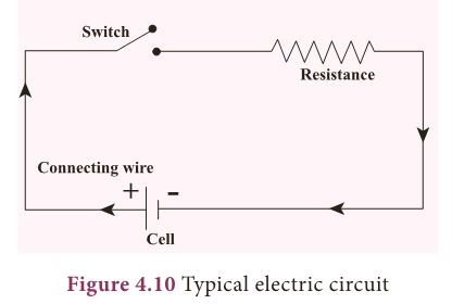
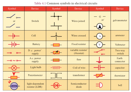
- To represent an electrical wiring or solve problem involving electric circuits, the circuit diagrams are made.
- The four main components of any circuits namely,
- cell,
- connecting wire,
- switch and
- resistor or load are given above.
- In addition to the above many other electrical components are also used in an actual circuit.
- A uniform system of symbols has been evolved to describe them.
- It is like learning a sign language, but useful in understanding circuit diagrams.
- Some common symbols in the electrical circuit are shown in Table 4.1.
Note:
- Difference between e.m.f and potential difference: As both e.m.f and potential difference are measured in volt, they may appear the same.
- But they are not. The e.m.f refers to the voltage developed across the terminals of an electrical source when it does not produce current in the circuit.
- Potential difference refers to the voltage developed between any two points (even across electrical devices) in an electric circuit when there is current in the circuit.
Different electrical circuits
- Look at the two circuits, shown in Figure 4.11.
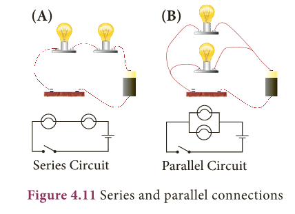
- In Figure A two bulbs are connected in series and in Figure B they are connected in parallel. Let us look at each of these separately.
Series circuits
- Let us first look at the current in a series circuit.
- In a series circuit the components are connected one after another in a single loop.
- In a series circuit there is only one pathway through which the electric charge flow.
- From the above we can know that the current I all along the series circuit remain same.
- That is in a series circuit the current in each point of the circuit is same.
Parallel circuits
- In parallel circuits, the components are connected to the e.m.f source in two or more loops.
- In a parallel circuit there is more than one path for the electric charge to flow.
- In a parallel circuit the sum of the individual current in each of the parallel branches is equal to the main current flowing into or out of the parallel branches.
- Also, in a parallel circuit the potential difference across separate parallel branches are same.
Effects of electric current
- When current flows in a circuit it exhibits various effects.
- The main effects are heating, chemical and magnetic effects.
Heating effect
Activity 2
- Cut an arrow shaped strip from aluminium foil.
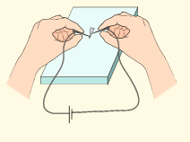
- Ensure that the head is a fine point. Keep the arrow shaped foil on a wooden board.
- Connect a thin pin to two lengths of wire.
- Connect the wires to the terminals of electric cell, may be of 9V.
- Press one pin onto the pointed tip and other pin at a point about one or two mm away. Can you see that the tip of aluminium foil starts melting?
Caution:

- The heating effect and the chemical effect experiments have to be performed only with a dc cell of around 9V.
- Students at any cost should not use the main domestic electric supply which is a 220V ac voltage.
- If it is used it will give a heavy electric shock leading to a severe damage to our body.
- When the flow of current is ‘resisted’ generally heat is produced.
- This is because the electrons while moving in the wire or resistor suffer resistance.
- Work has to be done to overcome the resistance which is converted in to heat energy.
- This conversion of electrical energy into heating energy is called ‘Joule heating’ as this effect was extensively studied by the scientist Joule.
- This forms the principle of all electric heating appliances like iron box, water heater, toaster etc.
- Even connecting wires offer a small resistance to the flow of current.
- That is why almost all electrical appliances including the connecting wires are warm when used in an electric circuit.
Chemical effect
Activity 3
- Take a beaker half filled with copper sulphate solution.
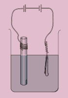
- Take a carbon rod from a used dry cell. Wind a wire on its upper end. Take a thick copper wire, clean it well and flatten it with a hammer.
- Immerse both the copper wire and carbon rod in the copper sulphate solution.
- Connect the carbon rod to the negative terminal of an electric cell and copper wire to the positive terminal of the cell.
- Also ensure that the copper and the carbon rod do not touch each other, but are close enough. Wait and watch.
- After some time you would find fine copper deposited over the carbon rod. This is called as electroplating. This is due to the chemical effect of current.
- So far we have come across the cases in which only the electrons can conduct electricity.
- But, here when current passes through electrolyte like copper sulphate solution, both the electron and the positive copper ion conduct electricity.
- The process of conduction of electric current through solutions is called ‘electrolysis’.
- The solution through which the electricity passes is called ‘electrolyte’.
- The positive terminal inserted in to the solution is called ‘anode’ and the negative terminal ‘cathode’.
- In the above experiment, copper wire is anode and carbon rod is cathode.
Magnetic effect of electricity
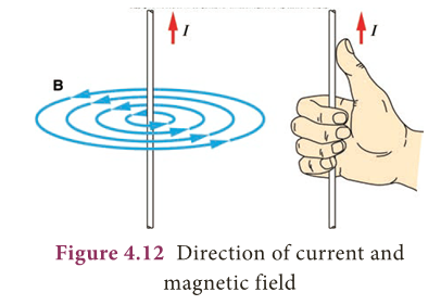
- A wire or a conductor carrying current develops a magnetic field perpendicular to the direction of the flow of current.
- This is called magnetic effect of current.
- The discovery of the scientist Oersted and the ‘right hand thumb rule’ are detailed in the chapter on Magnetism and Electromagnetism in this book.
- Direction of current is shown by the right hand thumb and the direction of magnetic field is shown by other fingers of the same right hand (Fig. 4.12).
Types of current
- There are two distinct types of electric currents that we encounter in our everyday life: direct current (dc) and alternating current (ac).
Direct current
- We know current in electrical circuits is due to the motion of positive charge from higher potential to lower potential or electron from lower to higher electrical potential.
- Electrons move from negative terminal of the battery to positive of the battery.
- Battery is used to maintain a potential difference between the two ends of the wire.
- Battery is one of the sources for dc current.
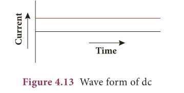
- The dc is due to the unidirectional flow of electric charges.
- Some other sources of dc are solar cells, thermocouples etc.
- The graph depicting the direct current is shown in Figure 4.13.
- Many electronic circuits use dc.
- Some examples of devices which work on dc are cell phones, radio, electric keyboard, electric vehicles etc.
Alternating current
- If the direction of the current in a resistor or in any other element changes its direction alternately, the current is called an alternating current.
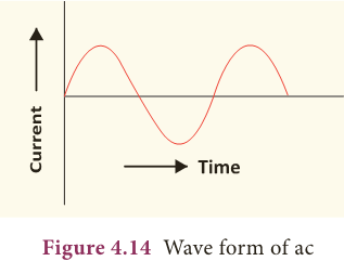
- The alternating current varies sinusoidally with time.
- This variation is characterised by a term called as frequency.
- Frequency is the number of complete cycle of variation, gone through by the ac in one second.
- In ac, the electrons do not flow in one direction because the potential of the terminals vary between high and low alternately.
- Thus, the electrons move to and fro in the wire carrying alternating current. It is diagrammatically represented in Figure 4.14.
- Domestic supply is in the form of ac. When we want to use an electrical device in dc, then we have to use a device to convert ac to dc.
- The device used to convert ac to dc is called rectifier.
- Colloquially it is called with several names like battery eliminator, dc adaptor and so on. The device used to convert dc into ac is called inverter.
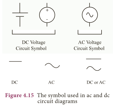
- The symbols used in ac and dc circuits are shown in Figure 4.15.
Advantages of ac over dc
- The voltage of ac can be varied easily using a device called transformer.
- The ac can be carried over long distances using step up transformers.
- The loss of energy while distributing current in the form of ac is negligible.
- Direct current cannot be transmitted as such.
- The ac can be easily converted into dc and generating ac is easier than dc.
- The ac can produce electromagnetic induction which is useful in several ways.
Advantage of dc
- Electroplating, electro refining and electrotyping can be done only using dc.
- Electricity can be stored only in the form of dc.
Dangers of electricity and precautions to be taken
- The following are the possible dangers as for as electric current is concerned.
- Damaged insulation: Do not touch the bare wire. Use safety glows and stand on insulating stool or rubber slippers while handling electricity.
- Overload of power sockets: Do not connect too many electrical devices to a single electrical socket.
- Inappropriate use of electrical appliances: Always use the electrical appliances according to the power rating of the device like ac point, TV point, microwave oven point etc.
- Environment with moisture and dampness: Keep the place, where there is electricity, out of moisture and wetness as it will lead to leakage of electric current.
- Beyond the reach of children: The electrical sockets are to be kept away from the reach of little children who do not know the dangers of electricity.
MORE TO KNOW:
Newton’s third law
- Electrostatic forces between two point charges obey Newton’s third law. The force on one charge is the action and on the other is reaction and vice versa.
Synaptic Signals
- Extremely weak electric current is produced in the human body by the movement of charged particles. These are called synaptic signals.
- These signals are produced by electro-chemical process.
- They travel between brain and the organs through nervous system.
The voltage and frequency of ac
- In India, the voltage and frequency of ac used for domestic purpose is 220 V and 50 Hz respectively where as in United States of America it is 110 V and 60 Hz respectively.
Resistance
- Resistance of a dry human body is about 1,00,000 ohm.
- Because of the presence of water in our body the resistance is reduced to few hundred ohm.
- Thus, a normal human body is a good conductor of electricity.
- Hence, precautions are required while doing electrical work.
EXTRA POINTS:
- Electric charge: It is the fundamental property of matter.
- Electric field: The region around a charge in which another charge experiences electric force.
- Electric lines of force: The electric lines of force are straight or curved paths along which a unit positive charge tends to move in the electric field.
- Electric potential: Measure of the work done on unit positive charge to bring it to that point against all electrical forces.
- Electric current: Electric current is the rate at which charges flow across a conductor in a circuit.
- Ammeter: An instrument used for measuring the amount of electric current.
- e.m.f: Work done by the electrical energy source in driving a unit charge around the complete circuit.
- Voltmeter: An instrument used to measure the potential difference.
- Resistance: The measure of opposition offered by the component to the flow of electric current through it.
- Resistors: Components used for providing resistance.
- Electrolyte: The solution through which electric current flows.
- Anode: The positive terminal in the electrolyte.
- Cathode: The negative terminal in the electrolyte.
- Alternating current: Current in a resistor or in any other element which changes its direction alternately.